electronics
Automotive Relay Tester
Arduino Nano relay tester for automotive diagnostics -- measures coil resistance, contact resistance, and activation time for 4-pin and 5-pin relays with pass/fail LED indicators.
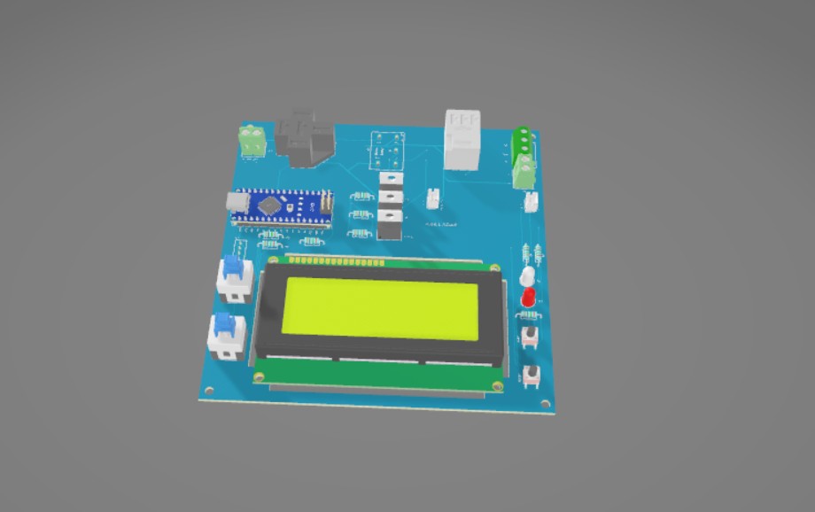
Arduino Nano-based relay tester built for automotive diagnostics. Tests 4-pin and 5-pin relays, measuring coil resistance, contact resistance, and activation time. Displays results on a 20x4 I2C LCD with green/red pass/fail LEDs.
Overview
Commercial relay testers are expensive and slow to use in a shop environment. This tester gives you everything you need at a glance -- coil resistance, activation time in milliseconds, and a clear pass/fail result. Built for daily use as an automotive mechanic.
Features
- 4-pin and 5-pin relay modes
- Single test (x1) and 10-cycle stress test (x10) modes
- Measures NC and NO contact resistance
- Measures relay activation time in milliseconds
- Green/red pass/fail LED indicators
- 20x4 I2C LCD display
- Serial output for logging
Test Modes
| Mode | Description |
|---|---|
| 4-pin x1 | Single NO contact test |
| 4-pin x10 | 10-cycle stress test -- each cycle triggers immediately on contact closure for realistic stress testing, reports averages |
| 5-pin x1 | Single NC and NO contact test |
| 5-pin x10 | 10-cycle NC and NO stress test -- each cycle triggers immediately on contact closure for realistic stress testing, reports averages |
Hardware
| Component | Details |
|---|---|
| Microcontroller | Arduino Nano |
| Display | 20x4 I2C LCD (address 0x27) |
| Pass indicator | Green LED |
| Fail indicator | Red LED |
| Sense circuit | Voltage divider with 1kohm reference resistor (measure actual value with a multimeter for best accuracy) |
Pin Definitions
| Pin | Function |
|---|---|
| A2 | Circuit sensor (voltage divider) |
| 3 | 4/5 pin mode select button |
| 4 | Relay coil activation |
| 5 | NO contact ground |
| 6 | NC contact ground |
| 7 | Test trigger button |
| 8 | Fail LED (red) |
| 9 | Pass LED (green) |
| 10 | x1/x10 mode select button |
| SDA/SCL | I2C LCD |
Schematic
See schematics/relay-tester-schematic.svg for the full wiring diagram.
How It Works
The sense circuit is a voltage divider -- a known reference resistor (nominally 1k ohm) in series with the relay contact being tested. Measure your actual resistor value with a multimeter and update RREF in the code for accurate resistance readings.
For x10 stress tests, the relay is cycled 10 times and the results are averaged -- useful for catching intermittent failures that a single test would miss. Each cycle triggers the next activation as soon as contact closure is detected rather than waiting a fixed delay, simulating real-world rapid switching conditions and putting genuine stress on the relay contacts and coil.
Libraries
- LiquidCrystal_I2C -- install via Arduino Library Manager
Flashing
- Open
src/relay-tester.inoin Arduino IDE - Install LiquidCrystal_I2C via Library Manager if not already installed
- Select Arduino Nano as the board
- Select your COM port
- Upload
License
CC BY-NC 4.0 -- free to use and modify for non-commercial purposes with attribution. Copyright (c) 2022 Paul Thillier