automotive
BMW K100 Gear Position Converter
ATmega328P signal converter for the BMW K100 -- translates the 3-wire V+ gear position output to 6 discrete outputs for aftermarket speedometers. One of my first PCB designs, built senior year of high school.
ATmega328P-based signal converter that translates the BMW K100's 3-wire V+ gear position output to 6 discrete GND-referenced outputs -- one per gear plus neutral -- for use with aftermarket speedometers and displays.
Overview
The BMW K100 outputs gear position as a combination of voltage signals across 3 wires. Most aftermarket speedometers expect a simpler 6-wire input with one dedicated wire per gear. This converter reads the 3-wire signal and drives the appropriate output pin for the current gear.
This was one of my first PCB design projects, built during my senior year of high school. I also wanted to build a breadboard Arduino from scratch -- this was a good opportunity to do both at once. The ATmega328P was flashed in an Arduino Uno's DIP socket then transferred onto the custom PCB.
Fair warning -- this is massively overengineered. The same logic could have been implemented with a handful of basic logic gates and no microcontroller at all. But it was a great learning project.
Signal Logic
The K100 gear signal is read via analog inputs with a threshold of 500 (out of 1023).
| Pin 1 | Pin 2 | Pin N | Gear |
|---|---|---|---|
| LOW | LOW | LOW | Neutral |
| LOW | LOW | HIGH | 1st |
| HIGH | LOW | LOW | 2nd |
| HIGH | LOW | HIGH | 3rd |
| LOW | HIGH | LOW | 4th |
| LOW | HIGH | HIGH | 5th |
| HIGH | HIGH | HIGH | No signal |
Why Not Logic Gates?
This could have been built with just a few basic logic gates and no microcontroller. The 3-wire input gives 8 possible states (2^3), of which 6 are valid gear positions. Each output is simply a boolean combination of the 3 inputs.
The equivalent gate logic for each gear:
| Gear | Logic Expression |
|---|---|
| Neutral | NOT(Pin1) AND NOT(Pin2) AND NOT(PinN) |
| 1st | NOT(Pin1) AND NOT(Pin2) AND PinN |
| 2nd | Pin1 AND NOT(Pin2) AND NOT(PinN) |
| 3rd | Pin1 AND NOT(Pin2) AND PinN |
| 4th | NOT(Pin1) AND Pin2 AND NOT(PinN) |
| 5th | NOT(Pin1) AND Pin2 AND PinN |
Each output would need one 3-input AND gate and up to three NOT gates (inverters). A single 74HC04 (hex inverter) and two 74HC11 (triple 3-input AND) chips would cover the entire circuit -- total cost under $1. Instead, an ATmega328P was used. No regrets.
Hardware
| Component | Details |
|---|---|
| Microcontroller | ATmega328P (custom PCB, breadboard Arduino style) |
| Programmer | Arduino Uno (chip flashed in DIP socket then transferred to custom PCB) |
| Input | 3-wire V+ gear position signal from BMW K100 |
| Output | 6 discrete digital pins (one per gear + neutral) |
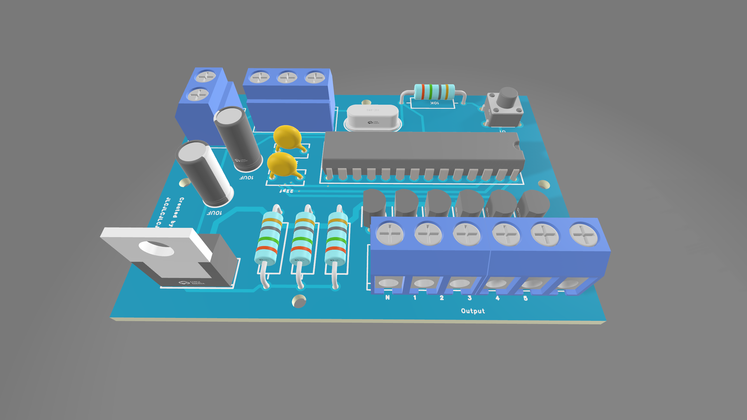
PCB
One of my first PCB designs -- a minimal ATmega328P circuit with only the components needed for this application. Designed and built during senior year of high school.
See pcb/ for design files and schematics/ for the schematic.
Pin Definitions
Inputs
| Pin | Function |
|---|---|
| 3 | Gear signal wire 1 |
| 4 | Gear signal wire 2 |
| 5 | Neutral signal wire |
Outputs
| Pin | Function |
|---|---|
| 8 | Neutral indicator |
| 9 | 1st gear indicator |
| 10 | 2nd gear indicator |
| 11 | 3rd gear indicator |
| 12 | 4th gear indicator |
| 13 | 5th gear indicator |
Files
| File | Description |
|---|---|
src/bmw-k100-gear-selector.ino |
Main firmware -- 6-wire output version |
src/bmw-k100-gear-selector-7seg-test.ino |
Development version -- drives a 7-segment display for bench testing |
Flashing
The ATmega328P was flashed directly in an Arduino Uno's DIP socket using the standard Arduino IDE, then removed and soldered onto the custom PCB.
To reflash:
- Remove the ATmega328P from the custom PCB
- Place it in an Arduino Uno's DIP socket
- Open
src/bmw-k100-gear-selector.inoin Arduino IDE - Select Arduino Uno as the board
- Select your COM port
- Upload
- Remove the chip and reinstall on the custom PCB
License
CC BY-NC 4.0 -- free to use and modify for non-commercial purposes with attribution. Copyright (c) 2021 Paul Thillier